
IoT Air Quality Sensor PCB
High-performance PCB powering smarter, healthier indoor environments.
Background
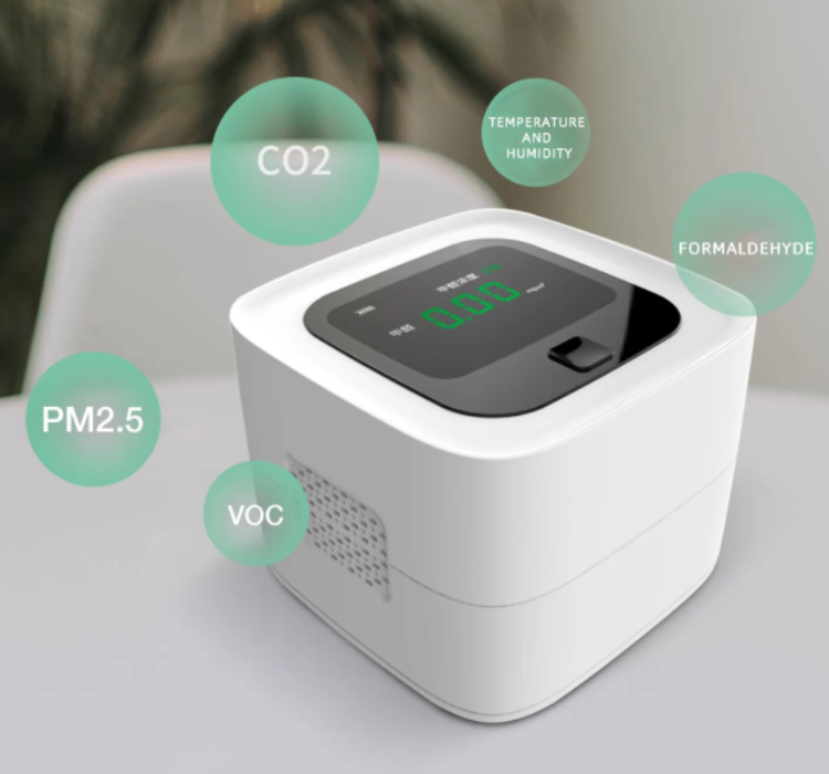
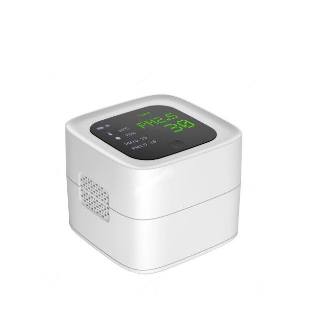
A UK-based smart home brand approached us to design and manufacture a compact PCB for their next-generation indoor air quality monitoring device. The product needed to measure PM2.5, CO₂, temperature, and humidity, and transmit data to a mobile app via Wi-Fi + Bluetooth Low Energy (BLE).
The brand was under pressure to launch within 9 months, as competitors were already rolling out new devices with multi-sensor integration and cloud connectivity.
The Challenge: A Buyer's Pain Points
The client's initial prototype was a collection of breakout boards and modules, proving the concept but failing on key commercial requirements.
Miniaturization & Integration
Their in-house design was too large to fit the sleek product housing. PCB needed to stay under 45mm × 45mm.
Signal Interference
Wi-Fi and BLE modules interfered with the PM2.5 sensor’s analog readings in early prototypes.
Power Efficiency
Device must run for >6 months on two AA batteries, requiring ultra-low power design.
Certification Pressure
Must comply with CE, RoHS, and EN 55032 EMC standards for European market approval.
Vision & Design Goals
- Ultra-compact PCB, ≤ 45mm × 45mm, optimized for plastic housing airflow
- Integration of PM2.5 sensor, CO₂ module, temperature & humidity sensors on a single board
- ESP32-based MCU for dual Wi-Fi + BLE connectivity
- Full compliance with CE/EMC/RoHS certification requirements
- Ready for scalable production: 5,000 → 30,000 units per year
Our Solution
- PCB Stack-up: 4-layer, 1 oz copper, ENIG finish
- RF Design: ESP32 module with carefully tuned 50Ω RF trace impedance
- Sensors: NDIR CO₂ sensor, PM2.5 laser scattering module, SHT35 humidity + temperature sensor
- Power Design: DC/DC buck regulator + LDO hybrid for efficiency & noise control
- Power Modes: <10 µA sleep current, ~150 mA peak TX current
- Shielding: Ground guard rings + EMI shielding can over RF + PM2.5 analog front end
Our Design & Development Process
Our proven process ensured every aspect of the design was optimized for performance and reliability.
Step 1 – Requirements Analysis
Reviewed airflow model of housing to ensure correct placement of sensors
Defined power budget < 200 µA average consumption
Set certification requirements (CE, EMC EN 55032, RoHS) early in design
Step 2 – Schematic Design
Chose ESP32-WROOM module (FCC/CE pre-certified)
Added load switch to power sensors only when sampling
Designed I²C + UART interfaces for multi-sensor data acquisition
Step 3 – PCB Layout & Routing
4-layer layout with dedicated ground plane
RF antenna trace tuned to 50Ω with controlled impedance
Analog + digital ground separated, joined at a single point near power input
PM2.5 sensor placed in airflow path, isolated from Wi-Fi antenna to reduce interference
Step 4 – SI/PI Analysis
Simulated RF interference coupling with PM2.5 sensor analog output → optimized ground shielding
Verified power ripple <15 mV at 3.3V rail during TX bursts
Step 5 – DFM/DFA Check
Ensured all components placed on top layer for single-pass SMT assembly
Verified stencil design for 0.4mm pitch ESP32 module
Connector alignment verified with client’s housing CAD
Step 6 – Prototyping & Testing
Produced 30 prototype boards
Thermal Test: PCB stayed <45°C under continuous Wi-Fi operation
Power Test: Achieved average current 180 µA → projected battery life ~14 months
EMC Pre-compliance Test: Passed EN 55032, margin ≥ 4 dB
Step 7 – Mass Production
Pilot run of 500 units delivered within 4 weeks
Scaling to 10,000 pcs/year, later expanding to 30,000 pcs/year with yield rate of 99.5%
Happy Clients!
How We Control Quality
Quality isn’t a checklist; it’s a culture. Our commitment is backed by:
- Comprehensive Testing: 100% AOI inspection + in-circuit test (ICT)
- Functional test: Wi-Fi/BLE pairing + sensor accuracy verification on each board
- Sample units tested in climatic chamber (-20°C to +60°C, 90% RH) to validate reliability
- Full RoHS 2.0 material traceability provided
